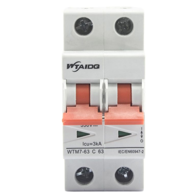
WTM7-125 DC Miniature Circuit Breaker 125A for 1000 V DC Feeders
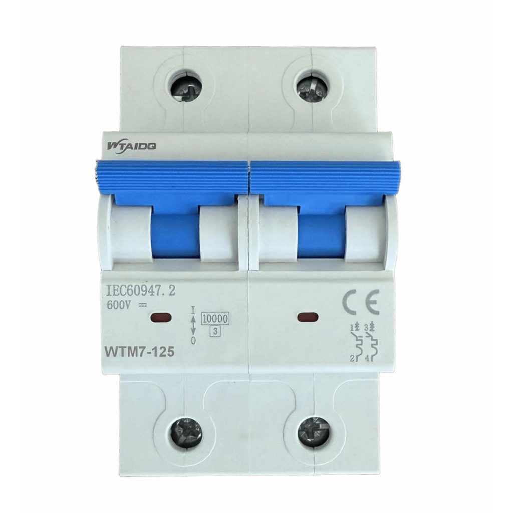
The WTM7-125 is a 125 A frame DC miniature circuit breaker for feeders and battery circuits on the direct current side of solar, storage and DC distribution systems. It reaches 1000 V DC on four poles, holds a 10 kA breaking capacity in a 27 mm module, and takes 50 mm² cable, so a DC feeder can be protected by a DIN rail device instead of a larger moulded case unit.
One frame from 32 A to 125 A
Seven ratings cover 32, 40, 50, 63, 80, 100 and 125 A on the same body. A panel can carry a 125 A incoming feeder and 32 A outgoing circuits from one product family, with matching accessories and one set of spare parts.
Voltage steps with the pole count
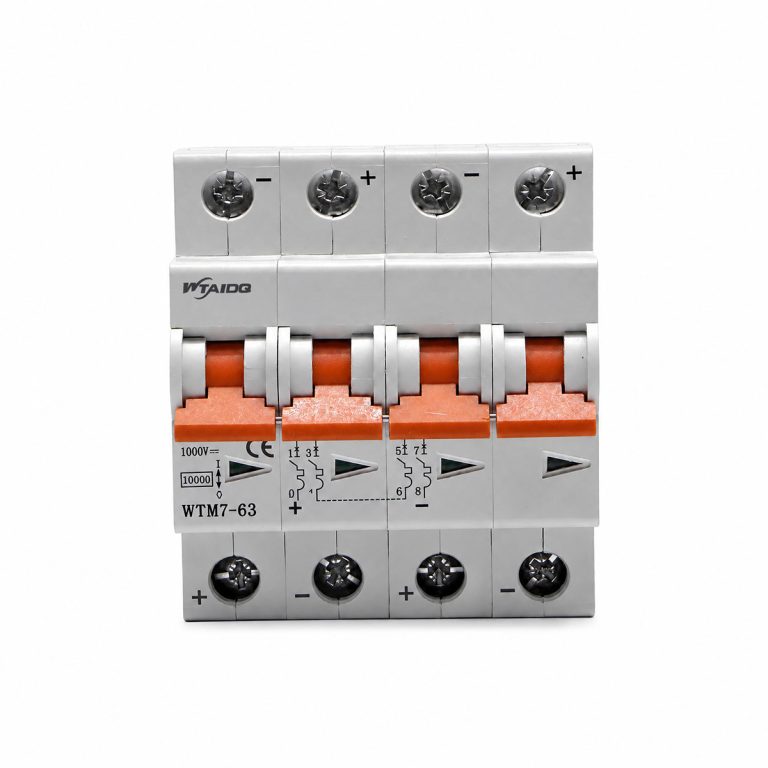
Rated voltage rises with the number of poles in series: 250 V DC at 1P, 500 V DC at 2P, 750 V DC at 3P and 1000 V DC at 4P. Select the pole count from the system voltage first, then the current rating from the load.
10 kA in a 27 mm module
Ultimate breaking capacity is 10 kA and the service breaking capacity is 7.5 kA, which covers fault levels on the DC side of string combiners and rack feeders. Insulation voltage is 1000 V and impulse withstand is 6 kV, so switching transients on a DC bus stay inside the device rating.
Three trip curves for three kinds of load
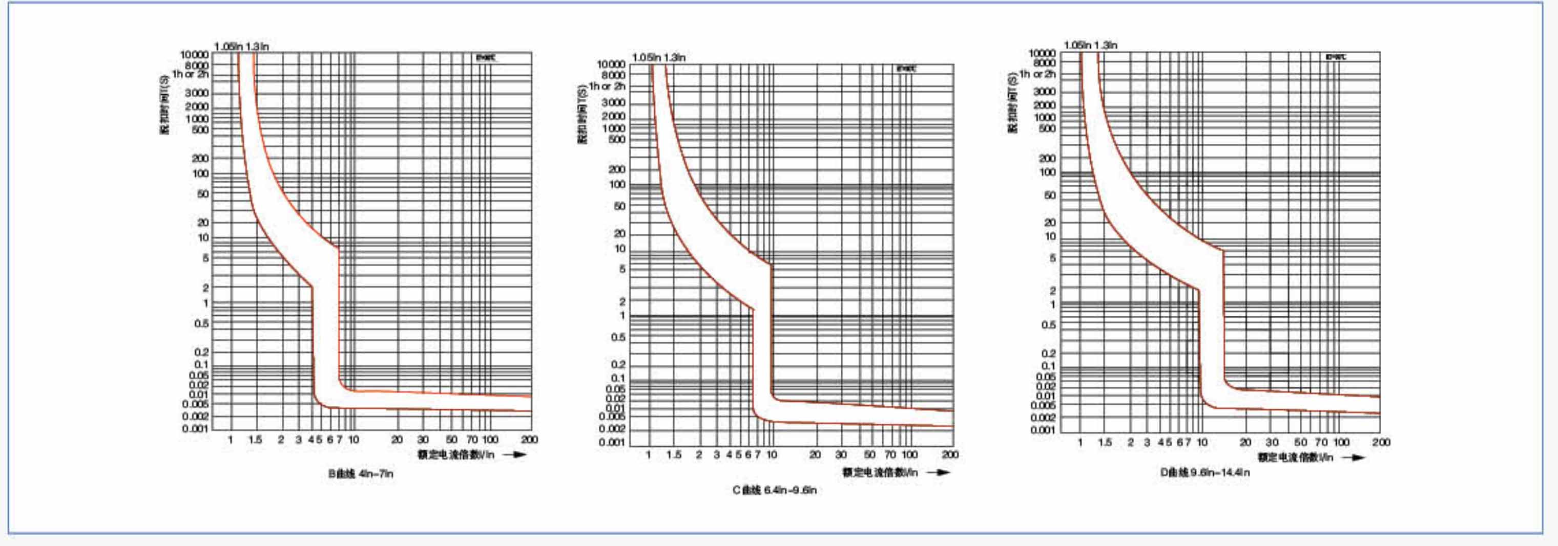
The B curve starts magnetic tripping between 4 and 7 In for cable and resistive DC loads, the C curve at 8 In plus or minus 20 percent suits mixed loads, and the D curve at 12 In plus or minus 20 percent rides through motor and capacitor inrush. Devices are calibrated at a reference ambient of 30 °C, and the trip unit carries no intentional short time delay.
Non-polarised terminals and panel fit
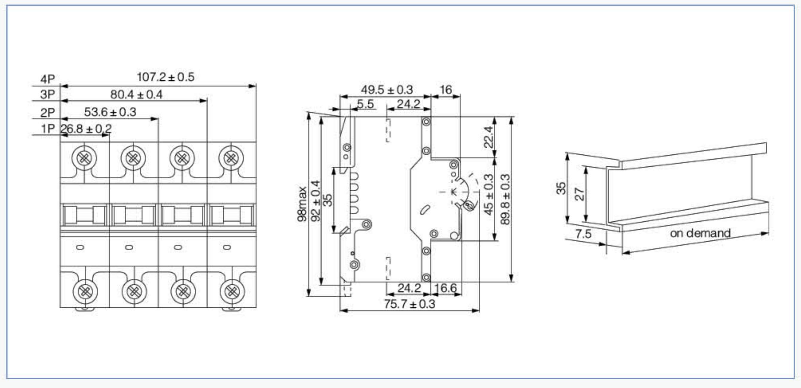
Line and load can be connected either way round, and the incoming feed may enter from the top or the bottom, so a reversed DC run does not have to be re-terminated. Terminals take 50 mm², each pole is 27 mm wide, the front is IP20, and the device clips to 35 mm DIN rail with a latch that gives enough travel to swap a breaker without dismantling the row.
Life and indication
Mechanical life is 20,000 operations and electrical life 1,500 operations at rated load. A contact position window on the front shows whether the contacts are open, which supports lock out work on a live DC board.
Send the system voltage, the feeder current and the fault level at the point of installation, and we will confirm the WTM7-125 pole count and rating to order.