Data center power distribution followed one pattern for two decades. Medium voltage AC entered the building, 415V or 480V AC reached the row, and a final conversion produced 54V DC at the rack. That pattern assumed rack density between 5 kW and 15 kW.
Accelerator racks moved past the range. As rack power approaches and exceeds 600 kW, distributing current at 54V stops being practical. Copper mass, conductor count and conversion losses no longer scale, and the final conversion stage becomes the problem rather than the solution.
This article covers what 800V DC distribution changes for the devices that switch and protect it, where electromechanical contactors remain the correct choice, and which values have to be settled before a quotation is issued.
How Rack Density Broke the 54V Distribution Model
At 54V, a 600 kW rack needs current in the range of eleven thousand amperes. Distributing that requires busbar cross sections and parallel conductor counts that do not fit a rack envelope, and each conversion stage adds loss that must be removed as heat. Raising distribution voltage divides the current by the same factor the voltage rises, which is why 800V DC removes the practical limit rather than simply improving efficiency.
The change also moves the boundary between the facility and the rack. Under the 54V design the final conversion happened inside the rack. Under 800V DC the conversion moves to a sidecar or to the row, and the rack receives a higher voltage that has to be switched and protected with the same discipline as the facility distribution.
Four Consequences for Switching Devices
Every device in the distribution path is affected, but four consequences decide the specification. Each one changes a value that appears on a datasheet, so each one belongs in the enquiry.
Arc extinction without a zero crossing
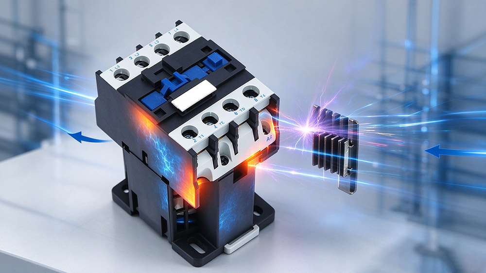
A DC arc does not self extinguish. At 800V and hundreds of amperes it sustains across an opening contact until the gap is long enough, or until the arc is driven into a splitter plate stack. A device rated AC 690V loses a large part of its breaking capability at 800V DC, so the DC rating must be read from a DC rating table at the application voltage.
Fault clearance speed
Protection coordination in AC systems is measured in cycles. On an 800V DC bus the converters and power supplies behind a fault have limited tolerance for sustained overcurrent, so clearing time becomes the design driver. Devices with a defined DC breaking time, and hybrid arrangements that combine a mechanical contact with a semiconductor path, exist for that reason.
Thermal behavior inside the rack
Higher voltage lowers I2R loss in the path but raises voltage stress on insulation and on the contact gap. A device carrying 800V DC must combine a high continuous thermal current with a defined DC breaking rating, and those requirements pull against each other in the geometry of the contact and arc chamber.
Bidirectional flow and hot swap duty
Racks increasingly include local energy storage and hot swap power shelves, which introduce bidirectional current and closing operations onto live capacitive loads. Pre-charge control and non polarized arc chambers become requirements rather than options.
What 800V DC Changes Inside the Rack
The rack level changes receive less attention than the distribution voltage, but they decide which devices can be installed inside the enclosure.
Busbar geometry and clearance
Higher voltage demands greater clearance and creepage distance between conductors and between a conductor and earth. Rack busbars designed for 54V do not carry the insulation distance that 800V requires, so the busbar assembly is redesigned rather than reused.
Connector and contact interface
At the same power, higher voltage means lower current, which reduces the conductor cross section needed. The voltage stress at the interface rises at the same time, so connector designs are assessed for dielectric strength as well as for current rating.
Insulation coordination
Insulation coordination on a DC bus is assessed against the highest sustained voltage rather than the nominal, because there is no zero crossing to relieve the stress. Transient overvoltage from the converters has to be added to that figure before the clearance is fixed.
Where Contactors Still Fit
Semiconductor switching covers the fastest protection layer, but three functions stay electromechanical. Each is characterized by infrequent operation and long periods of continuous current, which is where a mechanical contact performs best.
Isolation with a verifiable break
A mechanically open contact gives a visible and testable break for maintenance. Semiconductor devices leak, so they cannot serve as the isolation point a maintenance procedure requires.
Bulk source transfer
Source transfer and bus tie functions at row level are performed by high current contactors and automatic transfer equipment. These operate infrequently and hold continuous current for years, which favors a mechanical contact with low closed state resistance.
Battery and storage interfacing
The DC connection between a rack bus and a local battery is switched mechanically, because the device must hold continuous current at low loss across a long service life. Semiconductor switches there would need continuous cooling and would still leak.
Protection Coordination on an 800V DC Bus
Coordination on a DC bus is a different exercise from an AC distribution board. The fault current has no natural zero crossing, the clearing window is short, and the devices behind the fault have a limited tolerance for sustained overcurrent, so the sequence in which devices operate has to be proved rather than assumed.
Choosing the breaking device
The breaking device is selected on DC breaking current at the bus voltage, not on an AC rating carried across. Where the prospective fault current exceeds the rating of a single device, a hybrid arrangement splits the duty between a mechanical contact and a semiconductor path.
Proving coordination between layers
Coordination is demonstrated by comparing the time current curves of the devices in series at the actual DC voltage. Where a manufacturer cannot supply a DC curve, the device cannot be coordinated inside a documented study, and the design has to be changed rather than the study simplified.

Specification Points for 800V DC Devices
Seven values decide whether a device covers the duty. All of them belong in the enquiry before a quotation is issued.
- State the DC voltage rating explicitly, and confirm whether it is a breaking rating or an insulation rating.
- Confirm pole configuration, since reaching high DC voltage on a low voltage frame usually requires poles in series.
- Define making current, which on a capacitive load is set by the pre-charge design.
- Define the coil supply, and consider universal AC/DC coils so one spare part covers several cabinet types.
- Check the ambient inside the enclosure, because continuous current ratings assume a reference ambient and rack enclosures run hot.
- Confirm the certification basis, for example IEC/EN 60947-4-1 with UL 508 for North American deployment.
- State the required breaking time, since clearing speed rather than continuous rating governs the protection layer.
Frequently Asked Questions
No. The DC breaking rating is far lower than the AC rating, and the arc chamber is not built to stretch and split a sustained DC arc at that voltage.
For the same power, higher voltage means proportionally lower current. At 600 kW, 54V needs current that cannot be distributed with practical busbar mass.
Yes. DC designs use permanent magnet blowout and splitter plates to drive the arc from the contacts and divide it into short arcs that cannot sustain.
Pre-charge limits the current that flows when a contactor closes onto discharged capacitors. Without it, the first close can weld contacts or trip upstream protection.
Not for isolation. A semiconductor device leaks in the off state, so it cannot provide the verifiable break a maintenance procedure requires. Hybrid arrangements use both devices for their respective strengths.
From the source impedance: the upstream converter output impedance, the busbar impedance and the cable impedance. It is a calculated value, not a datasheet value.
Yes. Hot swap closing occurs onto a live capacitive load, so the making current is set by the pre-charge design and by the capacitance in the circuit, and it is usually the highest current the device will see.
Current becomes bidirectional, so a polarized arc chamber is unsuitable. A non polarized chamber, or an arrangement that guarantees polarity for each device, is specified instead.
It is an engineering response to a power density problem. The voltage class follows rack power, so the switching devices are specified against the rack requirement rather than against a fixed standard.
The New Standard for AI Rack Power
Driving massive power into a single server rack fundamentally rewrites the rules of electrical distribution. While moving to an 800V DC architecture elegantly solves the immediate copper and thermal bottlenecks, it transfers immense stress directly onto your switching and protection layers. The electromechanical contactors in these cutting edge facilities carry the ultimate responsibility for providing safe galvanic isolation while surviving severe continuous thermal loads and sudden capacitive strikes. Success in this era of extreme computing density requires completely abandoning legacy alternating current assumptions and specifying hardware engineered exclusively for the unforgiving realities of high voltage direct current.
Engineer Your Distribution Layer
Do not leave your critical power path to chance. Before you issue your final hyperscale specification, allow our technical experts to validate your switching hardware. Send us your target bus voltage, peak continuous current, spatial rack constraints, and required breaking times. We will recommend a precise contactor configuration that guarantees uncompromising safety and continuous uptime for your AI infrastructure. Connect with our engineering division or submit your project details via our contact page to build a truly resilient power network today.