Battery storage integrators write DC contactor specifications in a single line. It usually reads DC contactor, 1500V, 200A, and it goes to three suppliers who return three devices with different breaking capability, different arc control and different thermal behavior. The comparison then fails, because the line never defined the duty.
This guide covers what a contactor sees inside a storage container, which ratings decide whether a device survives its service life, and how pole configuration reaches high DC voltage on a low voltage frame.
What a Storage Contactor Actually Switches
A contactor in a storage string does not see a resistive load. It sees three different conditions across its service life, and a different rating governs each one.
The DC bus and its prospective fault current
The rack bus carries a defined prospective short circuit current set by the battery internal resistance, the cabling and the busbar layout. The main string contactor is the last mechanical element between the battery and that current, and it must open on it. Breaking rating at the actual bus voltage is the first number to confirm, and it is usually the lowest figure on the datasheet.
The PCS capacitor bank
The power conversion system presents a capacitor bank on the DC side. Without a pre-charge resistor and bypass path, the first close can reach many times nominal current and weld the contacts. The contactor then cannot open, and the failure is usually recorded against the contactor rather than against the missing pre-charge circuit.
The charge, discharge and idle cycle
A motor start is a short inrush followed by a steady run. A storage string holds near rated current for long periods, then reverses direction. The thermal design has to suit continuous current, while the arc design has to suit breaking in both directions. A device selected only on continuous current can pass the thermal check and still fail the arc check.
Why DC Switching Cannot Be Treated as AC Switching
The difference is not one of degree. It is a different arc extinction mechanism, and it changes which rating table a designer has to read.
No current zero crossing
An AC contactor relies on current passing through zero twice per cycle, which is why an AC-3 rated device can break several times its thermal current. Direct current has no zero crossing, so the arc must be stretched, cooled and forced into extinction by magnetic blowout and splitter plates. The gap is longer, the arc chamber is deeper, and the same frame therefore carries a much lower DC breaking rating than AC breaking rating.
The three current ratings
- Continuous thermal current (Ith). The current carried indefinitely inside an enclosure. It sets conductor sizing and terminal temperature rise.
- Making current. The current at the instant of closing. On a capacitive load it is set by the pre-charge design, not by the load.
- Breaking current. The current interruptible at rated DC voltage. Always the lowest of the three, and the one most often missing from a datasheet summary.
How Poles in Series Produce a High DC Rating
Low voltage contactor frames were developed for AC motor control, and their DC ratings are reached by arranging poles in series. Understanding how that arrangement produces the rating prevents two common errors: specifying too few poles, and assuming the poles can be wired in any order.
How series poles divide the voltage
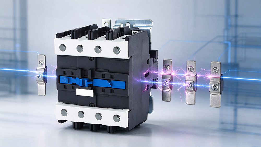
Each pole contributes an arc gap and a share of the total voltage. Four poles in series divide the bus voltage across four gaps, which is why a device rated DC 250V in single pole configuration can be listed at DC 1000V in four pole configuration. The rating belongs to the wiring arrangement as much as to the device, so the two have to be quoted together.
What the specification must state
A purchase specification for a storage string has to state the pole count, the series connection method and the terminal arrangement. Where the same device is also used for a parallel function elsewhere in the cabinet, the DC rating for that function has to be quoted separately, because the series rating does not transfer.
Four Specifications That Decide a BESS Contactor
Most selection failures trace back to one of these four, and each can be checked from a datasheet before an order is placed.
Rated DC voltage and pole configuration
Utility scale racks run 1000V to 1500V DC. Low voltage contactors reach these ratings by connecting poles in series, since each pole contributes an arc gap and divides the voltage. A device rated DC 250V in single pole reaches DC 1000V in four pole configuration. Pole count is part of the electrical rating, not a mechanical preference.
Duty cycle and thermal design
A rack performing two full cycles per day executes roughly 700 operations per year, and a device used for frequency regulation executes several thousand. Electrical endurance under load is typically an order of magnitude below mechanical endurance, and it determines the service interval. Silver alloy contacts resist welding and hold contact resistance low as the arc erodes the surface.
Arc suppression in bidirectional strings
Most storage systems charge and discharge through the same device. A polarized magnetic blowout, common in photovoltaic and electric vehicle designs, drives the arc in one direction only. On a bidirectional string, specify a non polarized arc chamber or a configuration that guarantees correct polarity per device.
Coil supply and contact material
Coil options are DC 24V, DC 48V, DC 110V and DC 220V, with universal AC/DC coils accepting either supply. Specify contact material, mechanical endurance and electrical endurance separately, since a datasheet listing only mechanical endurance describes the spring and armature rather than the contacts.
Common Field Failures and Their Cause
Three failure reports appear repeatedly in storage installations, and each traces back to a specification gap rather than to a manufacturing defect.
Contact welding on first close
Welding at commissioning points to making current above the contact rating. The pre-charge design, the resistor value and the bypass timing all have to be confirmed before the main contactor is energized for the first time.
Random sticking after months of service
Sticking that develops after service usually points to a polarized arc chamber in a bidirectional string, or to contact erosion from repeated breaking above the DC rating. Both are specification issues that appear only in operation.
Overheating at the terminal
Terminal overheating is a current density problem rather than a contactor problem. It tracks back to continuous current above the derated value for the enclosure ambient, or to a connection interface with insufficient contact area. The derating curve and the terminal torque figure both belong in the installation instruction.
Standards and Certification Checklist
The governing standard for low voltage AC and DC contactors is IEC/EN 60947-4-1, with GB 14048.4 as the Chinese equivalent and UL 508 for North American listings. A manufacturer able to supply test reports against all three reduces approval risk where a project must satisfy more than one market. Where the same DC bus also carries molded case breakers and surge protective devices, the protection coordination study is easier to defend when every device is certified to a named standard.
Frequently Asked Questions
No. DC breaking capability is far lower than the AC rating on the same device, and the arc chamber is not built for a sustained DC arc.
Poles are wired in series to divide DC voltage across several arc gaps. Reaching DC 1000V on a low voltage frame typically requires four poles.
Closing onto a capacitor bank without pre-charge, using a polarized blowout magnet on a bidirectional string, and welding from making current above the rating. Each has a different corrective action.
A DC coil holds constant current in both armature positions, so it dissipates power continuously. Electronic coil drivers and universal coils lower holding power and reduce temperature rise in a sealed enclosure.
DC bus voltage and pole configuration, continuous current, making current, breaking current, operations per day, coil voltage, enclosure ambient temperature, and the required certification markets.
No. A device rated for a higher DC voltage usually has a larger arc chamber and a lower continuous current rating for the same frame. The correct rating matches the bus voltage and the current, with the derating applied.
Continuous current ratings are quoted at a reference ambient, and high altitude reduces the dielectric strength of air. Both factors require derating, and both are common inside a container at a hot site.
Only if the making current of the bypass path is within the device rating. The pre-charge path closes onto a discharged bank and sees a much higher making current than the main string contactor, so the two duties usually take different devices.
The datasheet with the DC rating table, the derating curve, the endurance figures, the terminal torque specification, and the certificate numbers for the standards the project requires.
Finalizing Your Contactor Specification
Specifying a direct current contactor for a battery energy storage system requires moving far beyond a basic voltage and current wish list. Because storage environments force hardware to manage severe capacitive inrush, bidirectional power flows, and relentless thermal stress, a generic selection almost always guarantees premature field failure. The specific pole configuration, exact arc control method, and true breaking capacity must perfectly match the electrical reality of your storage rack. By locking down these operational duties early, system integrators can easily eliminate the severe risk of welded contacts and random switching failures.
Get Expert Specification Support
Stop guessing on your battery protection hardware. To have your storage contactor specification expertly verified against your actual system parameters, send our engineering team your precise bus voltage, continuous current, expected daily operations, and preferred pole configuration. We will ensure your direct current protection is specifically engineered to survive the exact extreme conditions inside your container. Reach out to sales@wtaiele.com or visit our contact page to secure the correct components for your project today.