Auxiliary contacts may be small components, but they help contactors work smoothly with control systems, indicator lights, and protective circuits. Understanding their contact states and configurations makes it easier to choose the right arrangement for a new panel or an existing installation.
Key Takeaways
Auxiliary contacts are used in control circuits for electrical signaling, interlocking, self-holding, and equipment status feedback. They do not normally carry the main load current of a motor.
NO (Normally Open) contacts close when the contactor operates, while NC (Normally Closed) contacts open when it operates, assuming standard mechanically linked operation.
A 1NO 1NC contactor provides one normally open and one normally closed auxiliary contact, making it useful for basic control and feedback circuits.
What an Auxiliary Contact Actually Does
A contactor generally contains two functional parts: a main circuit that switches electrical power to equipment and a control circuit that operates the contactor coil. Auxiliary contacts belong to the control and signaling side of this arrangement.
Main contacts are designed to switch the load connected to the contactor, such as a three-phase motor, pump, fan, or compressor. Their ratings are selected according to the load current, operating conditions, and applicable utilization category.
Auxiliary contacts serve a different purpose. They provide an electrical signal that reflects the contactor’s operating state or supports control logic. For example, an auxiliary contact can energize a pilot light when a contactor closes, provide a holding path after a start button is released, or prevent two contactors from operating at the same time.
This distinction explains the auxiliary contact meaning in practical terms: it is a supplementary switching contact used for control, signaling, or interlocking rather than for carrying the primary load.
NO and NC on a Contactor
NO and NC describe the contact’s normal state, meaning its state when the contactor is not energized under standard operating conditions. They do not describe whether the contact is permanently open or closed.
An NO contact is open when the contactor coil is de-energized. When the coil energizes and the contactor operates, the NO contact closes, allowing current to flow through the auxiliary circuit.
An NC contact behaves in the opposite way. It is closed when the contactor is de-energized and opens when the contactor operates.
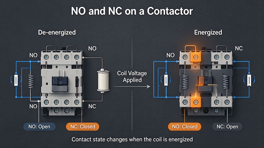
| Contact Type | Contactor De-energized | Contactor Energized | Common Application |
|---|---|---|---|
| NO | Open | Closed | Run indication, self-holding, operating feedback |
| NC | Closed | Open | Electrical interlocking, stop logic, status signaling |
| 1NO+1NC | One open, one closed | One closed, one open | Combined control and feedback |
Common Auxiliary Contact Configurations
The number and type of auxiliary contacts determine how many control functions can be handled directly by a contactor. The right arrangement depends on the wiring diagram, the number of signals required, and whether the circuit needs both NO and NC contacts.
| Configuration | Contact Arrangement | Typical Use |
|---|---|---|
| 1NO | One normally open contact | Run indication or self-holding |
| 1NC | One normally closed contact | Interlocking or off-state signaling |
| 1NO+1NC | One NO and one NC | Combined control and status feedback |
| 2NO+2NC | Two NO and two NC | Multiple control and signaling functions |
What Does 1NO 1NC Contactor Meaning Actually Tell You?
The 1NO 1NC contactor meaning is that the device provides one normally open auxiliary contact and one normally closed auxiliary contact. When the contactor changes state, these contacts switch according to their designed operating sequence.
A 1NO 1NC contactor is a practical option when a control circuit needs two different signals. For instance, the NO contact can illuminate a green run indicator, while the NC contact can provide a signal to another control circuit when the contactor is released.
Side-Mount vs. Top-Mount Auxiliary Contact Blocks
An auxiliary contact block adds supplementary contacts to a compatible contactor. It can be useful when the standard contact arrangement does not provide enough NO or NC contacts for the planned circuit.
Choosing the Mounting Position
Side-mounted and top-mounted designs are shown here as general installation options.
Side-Mounted Block
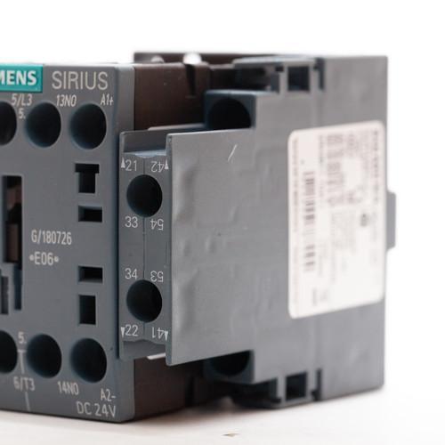
Attaches to a compatible side face of the contactor. It may be convenient when the top is reserved for wiring or when the product design supports side expansion.
Top-Mounted Block
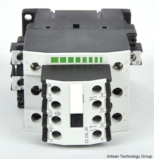
Fits above the contactor on compatible models. It can provide an alternative where side clearance is limited, although additional vertical space is required.
Neither mounting style is universally better. The decision comes down to the contactor’s mechanical design, available panel space, wiring access, and the number of contacts required.
Rated Values and Why Auxiliary Contacts Cannot Switch a Motor
Auxiliary contacts are intended for control duties, not as substitutes for a contactor’s main power poles. Their electrical ratings must be assessed separately from the contactor’s main current rating.
Understanding AC-15 and DC-13 Ratings
A contactor may have a main circuit rating of several tens of amperes, but its auxiliary contacts can have a much lower rated operational current. The rating depends on the product and the utilization category.
AC-15 is commonly associated with controlling electromagnetic loads in AC control circuits, while DC-13 covers relevant electromagnetic control loads on DC circuits. These categories account for switching conditions that differ from those of simple resistive loads.
Some auxiliary contacts may be marked with a conventional thermal current of 10 A, but this does not mean they can switch every 10 A load under all conditions. Their permitted operational current depends on factors such as voltage, load type, utilization category, and the manufacturer’s data. A specific model may have an AC-15 rating below 10 A.
Three Common Ways to Use Auxiliary Contacts
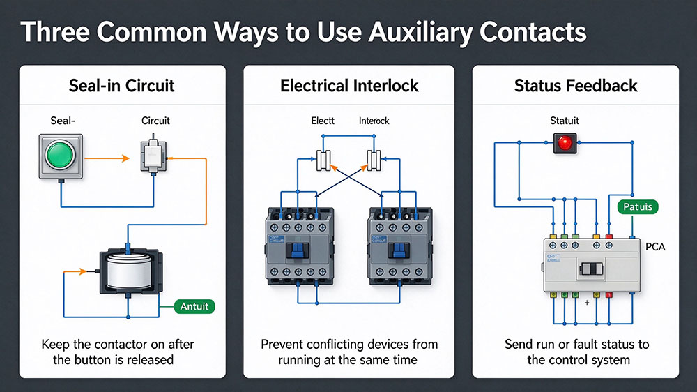
Auxiliary contacts become easier to select when you start with the circuit’s intended behavior. Three common applications are self-holding, interlocking, and status feedback.
1. Self-Holding Circuits
In a typical motor starter circuit, pressing the start button energizes the contactor coil. An NO auxiliary contact wired in parallel with the momentary start button then closes, providing a holding path that keeps the coil energized after the button is released.
When the stop circuit opens or the control supply is interrupted, the coil de-energizes and the auxiliary contact returns to its normal state. The holding path is removed, so another start command is required.
2. Electrical Interlocking
Auxiliary contact interlocking prevents incompatible commands from energizing two contactors simultaneously. A common example is a forward/reverse motor starter.
An NC auxiliary contact from the reverse contactor is wired in series with the forward contactor’s coil. When the reverse contactor operates, its NC contact opens, interrupting the forward coil circuit. A corresponding NC contact in the forward circuit prevents the reverse contactor from energizing at the same time.
3. Status Feedback
An auxiliary contact can send a signal to a PLC, indicator lamp, alarm circuit, or building management system. For example, an NO contact may close when the contactor operates, allowing the control system to register an auxiliary indication that the contactor has been commanded into its energized position.
Keep in mind that this is contactor-state feedback, not definitive proof that the motor is rotating or that all main poles are conducting correctly.
Auxiliary Contact vs. Auxiliary Relay
Although their names sound similar, auxiliary contacts and auxiliary relays serve different roles in a control circuit.
| Comparison Item | Auxiliary Contact | Auxiliary Relay |
|---|---|---|
| Definition | An individual switching contact associated with a contactor or an add-on contact block. | A separate electromechanical or electronic device with its own control input and switching contacts. |
| Operating Principle | Follows the operating mechanism of the associated contactor. | Operates independently in response to its own control signal. |
| Main Purpose | Provides additional signaling or control functions within a contactor circuit. | Adds switching contacts, supports multiple control signals, or accommodates different control circuit arrangements. |
| Typical Application | Sends a signal from a contactor’s auxiliary contact to an interposing relay. | Provides multiple isolated switching paths for other control devices, provided its contact arrangement and ratings are suitable. |
| PLC Interface | Can provide contact status feedback to a PLC, depending on the circuit design. | Can allow a PLC output to control a separate circuit without directly switching the contactor coil. |
| Selection Considerations | Check the contact configuration, electrical ratings, and compatibility with the contactor. | Check coil voltage, current, switching frequency, isolation requirements, contact configuration, and electrical ratings. |
How to Specify Auxiliary Contacts on a Purchase Order
A clear purchase order should identify the contactor, the required auxiliary configuration, and any additional electrical or mechanical requirements. This reduces the risk of receiving a product that fits physically but does not match the intended circuit.
A Practical Specification Checklist
Before placing an order, confirm the following:
Contactor series and model: Specify the exact product family and model number.
Contact configuration: State 1NO, 1NC, 1NO+1NC, or 2NO+2NC as required.
Built-in or add-on contacts: Clarify whether the contacts must be integrated or supplied as a separate auxiliary contact block.
Mounting position: Specify side-mounted or top-mounted where applicable.
Electrical ratings: Confirm rated operational voltage and current for the actual utilization category, such as AC-15 or DC-13.
Coil voltage: Include the required coil voltage and AC or DC supply type for the contactor itself.
Compatibility: Confirm the auxiliary block is approved for the selected contactor model.
Quantity and documentation: State the required quantity and request the relevant datasheet or wiring diagram.
Conclusion
Choosing auxiliary contacts starts with understanding the control circuit. Once you know whether you need self-holding, interlocking, status feedback, or a combination of these functions, selecting the contact arrangement and mounting style becomes much more straightforward. Always verify the electrical ratings and product compatibility before installation.
For reliable low-voltage electrical control, explore WTAIELE’s contactor range to find options for different panel and motor-control applications.
Frequently Asked Questions
What does 1NO 1NC mean on a contactor?
It means the contactor has one normally open auxiliary contact and one normally closed auxiliary contact. When the contactor operates, the NO contact closes and the NC contact opens under standard operating conditions. This combination is commonly used for control logic and status indication.
Can I add an auxiliary contact block to any contactor?
No. The block must be compatible with the specific contactor series and model. Check its mounting position, permitted contact combinations, electrical ratings, and installation instructions before ordering.
Can an auxiliary contact switch a motor directly?
An ordinary auxiliary contact is not designed to replace the main contacts used for motor switching. Use appropriately rated main power contacts or a suitable motor-switching device, and select auxiliary contacts according to their control-circuit ratings.
Is an NC auxiliary contact suitable for interlocking?
Yes. An NC auxiliary contact is commonly wired in series with another contactor’s coil circuit to prevent simultaneous operation. Where the application calls for additional protection, use the appropriate mechanical interlock and safety measures as well.
What should I specify when buying a 1NO 1NC contactor?
Provide the contactor model, coil voltage and supply type, required 1NO+1NC arrangement, whether the contacts are built-in or supplied through an auxiliary contact block, and the applicable voltage and current ratings. Confirm mounting compatibility and request a wiring diagram if needed.