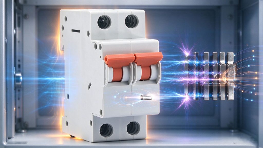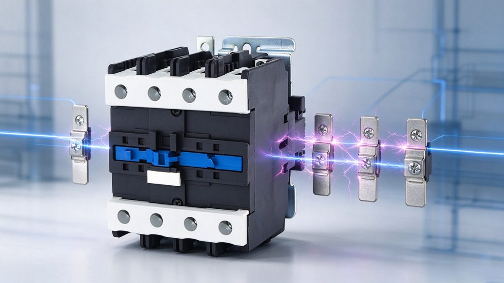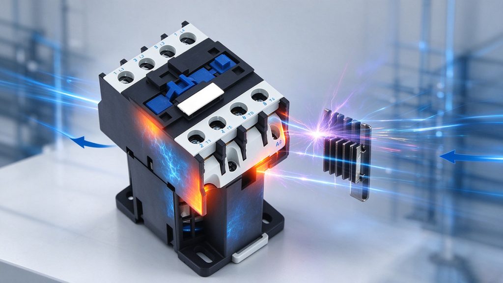
A contactor coil is usually treated as a fixed overhead in a control panel. It is not fixed. An alternating current coil naturally changes impedance as the armature physically closes, meaning the sealed holding current falls safely below the initial pull-in current. A direct current coil behaves entirely differently. Its current is set by fixed resistance alone, so it draws close to the exact same power in both positions. That trapped power is continuously dissipated as heat inside your enclosure for as long as the contactor stays energized.
This thermal effect appears in three distinct places. It shows up in the rising temperature inside the panel, in the inflated rating of the control transformer, and in the annual energy figure that reaches the facility energy management report. This engineering guide covers where this power loss originates, how to precisely measure it, and how to engineer it out of your system.
The Physics of Coil Power Dissipation
The two coil types behave in opposite ways when the armature physically moves. In an alternating current coil, closing the armature completes the magnetic circuit and raises impedance, dropping the sealed current well below the pull-in current. In a direct current coil, the physical armature position does not change the electrical resistance. The sealed current stays dangerously close to the pull-in value, and full power dissipation continues indefinitely.
All of this holding power appears exclusively as heat inside the closed enclosure. It never reaches the load. In a dense panel featuring twenty energized contactors, total holding power becomes a permanent parasitic heat load that your active air conditioning must constantly fight. The true financial cost of coil loss includes the cooling energy required just to remove the coil energy.
Measuring the True Heat Load
Before selecting a reduction strategy, the existing thermal figure must be established. You can map the exact heat load in three straightforward steps without modifying any device:
| Measurement Step | Action Required | Engineering Value |
|---|---|---|
| 1. Clamp meter reading | Measure coil current on an energized device and multiply by coil voltage. | Reveals true holding power. Compare against the datasheet, as undervoltage draws higher current. |
| 2. Total panel figure | Sum the holding power of every contactor energized simultaneously. | Provides the exact continuous heat load required for your panel thermal calculation. |
| 3. Auxiliary load isolation | Subtract the coil total from the measured panel auxiliary load. | Shows exactly how much standby consumption belongs purely to the coils versus other hardware. |
Three Core Strategies to Eliminate Coil Loss
Instead of accepting coil heat as an unavoidable reality, engineers can deploy three distinct strategies to optimize panel efficiency. These methods can be deployed individually or layered together depending on the application.
Strategy 1: Active Current Reduction
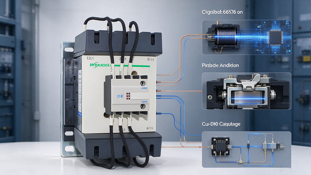
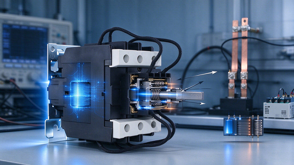
The most direct method is utilizing electronic coil drivers. An electronic driver applies full nominal voltage to powerfully pull in the armature, then drastically reduces the holding voltage once the contactor has sealed. Because the magnetic circuit is fully complete at that point, a much lower current easily maintains the closed position. Pull-in performance remains completely unaffected since full voltage remains active during the critical closing stroke.
Strategy 2: Zero Energy State Retention
For applications holding one specific state for long periods, mechanical latching represents the ultimate efficiency upgrade. A latching device consumes absolutely zero holding power once it is set. While it does not suit rapid switching duty, it removes coil loss entirely for static functions like source selection, bus tie connections, and seasonal load switching.
Strategy 3: Hardware and Supply Optimization
Optimizing your actual control supply architecture yields massive compounding benefits. Utilizing universal coils allows the exact same device to accept either an alternating or direct current control supply. This completely removes the bulky external rectifier module a standard direct current supply would otherwise require. Furthermore, if you are designing a direct current control bus, selecting the highest suitable coil voltage reduces the raw holding current required for the exact same holding power, instantly reducing the thermal stress on your internal wiring.
Specifying for Efficiency Without Losing Reliability
Reduced consumption must never reduce pull-in force. The contactor still must close reliably at the absolute minimum control voltage and the lowest expected ambient temperature, and it must effortlessly carry and break the rated load.
Before any reduced consumption option is selected, you must confirm the pull-in and drop-out voltages at both temperature extremes. A reduced holding circuit behaves differently during a sudden supply dip than a plain coil. Where a contactor dropping out mid-cycle would violently stop a production line, the reduced consumption option may require a modified control arrangement rather than just a simple device swap.
Frequently Asked Questions
An alternating current coil sees rising impedance as the magnetic circuit securely closes, forcing the sealed current to fall. A direct current coil is limited by resistance only, so its current stays close to the initial high value, creating continuous heat.
Holding voltage is reduced only after the armature has physically sealed. The magnetic holding force needed at that point is vastly lower than the initial pull-in force. However, drop-out voltage and chatter behavior must still be strictly verified by the engineer.
Absolutely all holding power appears as heat inside the closed enclosure. To find the total, sum the coil power across the panel, add it directly to your thermal calculation, and then add the extra cooling energy required to actively remove it.
Yes. Insulation aging and moisture ingress alter internal coil resistance and will raise the current draw over time. A coil that measures significantly higher than its published datasheet figure is a prime candidate for immediate replacement before it fails open circuit.
Eliminate Parasitic Heat from Your Panel Design
Modern dense panel architecture leaves absolutely zero room for parasitic heat loss. Allowing outdated direct current coils to continuously bake your internal components destroys hardware lifespan and inflates your facility cooling costs. By upgrading to active current reduction, zero energy mechanical latching, or optimized supply hardware, you can instantly slash your auxiliary power draw and drastically extend the life of your entire control cabinet.
Secure Your Efficiency Upgrade Today
WTAIELE delivers complete OEM and ODM custom solutions engineered specifically for your industrial control environment. Send our technical team your exact contactor frame requirements, precise coil voltage, expected duty cycle, and maximum internal ambient temperature limits. We will return a fully customized low consumption quotation within 24 hours.