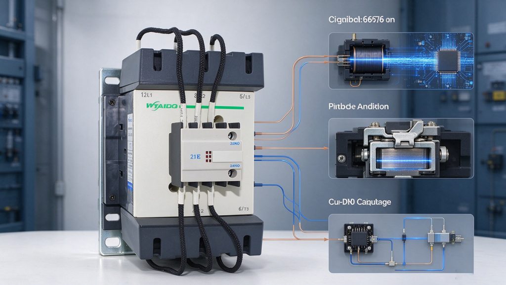
Heavy commercial electric trucks absolutely cannot rely on passenger vehicle charging architectures. Returning hundreds of kilowatt hours to a forty-ton vehicle within a strict mandatory driver rest period pushes electrical demand directly into the megawatt range. The Megawatt Charging System standard explicitly defines this extreme interface, and it fundamentally rewrites the rules for electrical distribution.
Charging voltage now moves to 1000V DC and beyond, while operating current routinely exceeds 1000A. A switching device rated for a standard 400V or 800V DC passenger station will instantly fail here because direct current breaking capability plummets as the application voltage rises. Furthermore, commercial depot charging requires prolonged continuous current within a tightly packed and power dense cabinet, making severe thermal derating a daily engineering reality rather than a rare edge case.
Here is exactly what engineers must consider when specifying contactors for the megawatt era.
Mapping the Internal Switching Architecture
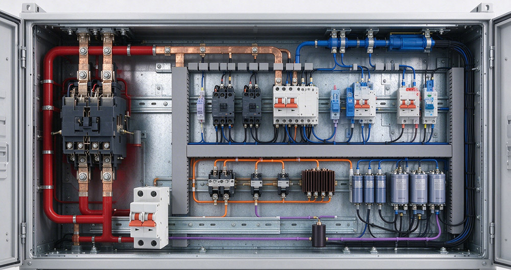
A commercial megawatt cabinet is an ecosystem of precise switching roles, not a single monolithic switch. Forcing one over-specified contactor to handle every single task usually compromises system reliability and inflates costs. You need to assign the right component to the right job:
The Main Supply Isolation
This heavy contactor connects the cabinet directly to the grid supply, providing a critical mechanical air gap for safe maintenance. Its engineering prioritizes massive continuous current holding rather than frequent mechanical cycling.
The Output Interface
Connecting the cabinet to the heavy vehicle inlet, this contactor only closes after strict insulation monitoring and precise voltage matching. Because it closes directly onto an active DC bus, it must effortlessly handle severe making current without welding its contacts.
The Pre-Charge and Discharge Paths
A dedicated smaller contactor paired with a heavy resistor safely charges the massive vehicle-side capacitance before the main output engages. The exact design of this pre-charge path dictates the ultimate making current the main output contactor must survive. Conversely, the discharge path safely drains all residual DC bus capacitance after a session completes, ensuring the physical connector is entirely de-energized before the driver separates it.
Why Bidirectional Operation Changes the Arc Chamber
Vehicle to grid and depot energy management require current in both directions through the same DC contactor. A polarized magnetic blowout is optimized for one direction, so a device built for unidirectional charging may fail to extinguish the arc when current reverses. For bidirectional megawatt charging, specify a non polarized arc chamber, or use a circuit arrangement that guarantees correct polarity per device. This is a specification decision, not a field adjustment.
How MCS Differs from Passenger Car Charging
The voltage and current class of a megawatt session changes more than the cable size. Three differences decide which devices can be used.
Voltage and current class
Passenger car DC charging commonly runs at 400V or 800V DC. Megawatt charging moves to 1000V DC and above, with current approaching and exceeding 1000A. A device rated for the lower class does not transfer to the higher one, because DC breaking capability falls as the application voltage rises.
Cooling and duty
A megawatt session runs for a longer continuous period than a passenger car session, and the cabinet is power dense. Continuous current at the cabinet ambient, rather than peak current for a short session, becomes the limiting figure.
Connector and cable interface
At 1000A the terminal interface, the cable cross section and the contact resistance all contribute to temperature rise. The contactor terminals are specified together with the connection hardware, because a correct device on an undersized interface still overheats.
Four Specifications That Decide an MCS Contactor
Four values decide whether a device covers the duty. All four must be quoted at the application voltage and the cabinet ambient, not at reference conditions.
Continuous current at the cabinet ambient
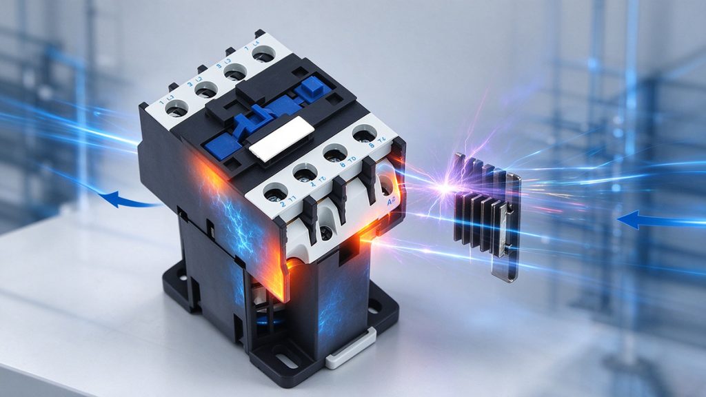
Megawatt cabinets are power dense, and the contactor sits beside converters and magnetics. Ratings are quoted at a reference temperature, so the derating curve must be applied honestly. A device rated 500A at 40 degrees C may be limited to a fraction of that inside a cabinet at 60 degrees C.
DC breaking capacity at 1000V or above
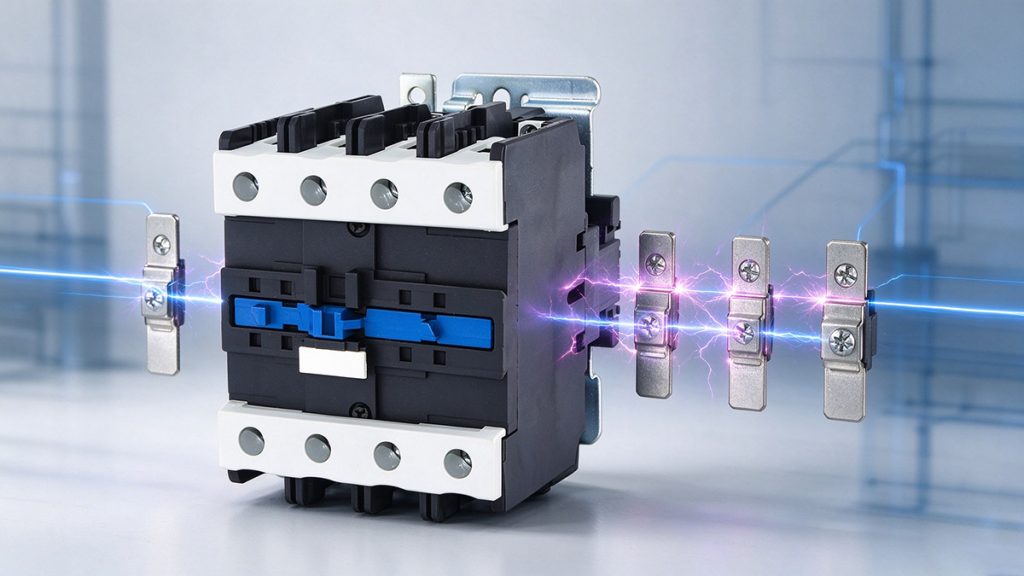
Breaking a DC arc at 1000V and hundreds of amperes requires a purpose built arc chamber, rated at the application voltage. Where a low voltage frame is used, poles are connected in series to divide voltage across several arc gaps, which is how a device rated DC 250V in single pole reaches DC 1000V in four pole configuration.
Making current and welding resistance
Closing onto a vehicle with significant input capacitance produces a current spike limited by the pre-charge design and cable impedance. Silver alloy contacts with high welding resistance are used here, because a welded contact means a service visit and a stranded vehicle.
Endurance expressed in charging sessions
A depot charger running twenty sessions per day executes more than 7,000 operations per year. Mechanical endurance in the 50,000 to 100,000 range and electrical endurance at rated DC load both need checking against the intended service interval.
Installation and Commissioning Checks
Commissioning failures in megawatt cabinets follow a small number of patterns. Three checks catch most of them before the first paid session.
Pre-charge verification
Measure the pre-charge current and the time taken to reach the matching voltage. If the resistor value or the bypass timing is wrong, the main contactor absorbs the difference on every close, and the erosion accumulates faster than the endurance figure predicts.
Insulation and polarity checks
Verify insulation resistance on the DC bus before energizing, and confirm the polarity arrangement of every device where a series string is used. A reversed device in a series string carries the full voltage across a single gap.
Thermal verification under load
Run a full power session and record terminal temperature, not cabinet air temperature. Terminal temperature rise above the design value points to a connection issue before it points to a device issue.
Procurement Checklist
- Charging voltage class, and the DC breaking voltage required at that class.
- Continuous DC current, with the derating curve for cabinet internal ambient.
- Making current, and the pre-charge design that limits it.
- Current direction, stated explicitly.
- Coil voltage and acceptable holding power.
- Endurance at rated load, converted to expected service years.
- Certification basis: IEC/EN 60947-4-1 with GB 14048.4, and UL 508 for North America.
- Terminal interface and the cable or busbar hardware that connects to it.
Frequently Asked Questions
A motor contactor is rated for AC-3 duty with a defined overload profile. A charging contactor handles sustained DC current at high voltage, with making current set by capacitive inrush and breaking current set by fault conditions.
Bidirectional current reverses the arc driving direction, so a polarized blowout magnet may fail to extinguish the arc. Non polarized arc chambers are specified instead.
Only if continuous, making and breaking current ratings all cover the higher power case at the cabinet ambient temperature.
Count sessions per day, multiply by operating days per year, and compare with electrical endurance at rated DC load. Mechanical endurance alone overstates life because it excludes arc erosion.
Yes. DC breaking capability falls as the application voltage rises, and the continuous current class is higher. A device rated for a car charger does not transfer to a truck charger.
The main output contactor absorbs the difference on every close. Contact erosion accelerates, and the failure appears as welding or as a device that will not open.
Parallel contacts share current unevenly unless the design accounts for it, and the first contact to open carries the full arc. Series connection for voltage and a single correctly rated device for current is the more predictable arrangement.
A DC rating table at the application voltage, the making and breaking current at that voltage, the derating curve against ambient, mechanical and electrical endurance, and the certification numbers for the standards the project lists.
It sets the voltage and current class, and therefore the breaking voltage the contactor has to be rated at. The device is then selected against that class rather than against the connector interface alone.
Secure Your Megawatt Switching Hardware
WTAIELE offers full OEM and ODM custom solutions, with all standard products carrying a comprehensive 12 month warranty.
To receive an accurate quotation within 24 hours, provide our engineering team with your charging voltage class, continuous DC current at true cabinet ambient, pre-charge design limits, required current direction, and target service years.