Choosing a contactor involves more than matching an ampere value to a motor or electrical circuit. Voltage, phase configuration, coil specifications, and switching duty all affect whether a device is suitable for its intended application. Understanding these ratings makes it easier to compare products, read nameplates, and avoid common selection mistakes.
Why Rated Current Alone Is Not Enough
Rated current is often the first figure people look for when comparing contactors. However, the current printed in a product catalog does not necessarily represent the current the device can switch safely under every operating condition.
The permissible current depends on the contactor’s design, operating voltage, load characteristics, and utilization category. A resistive heater, for example, presents a completely different switching duty from an induction motor that draws a high starting inrush current.
Continuous Current and Switching Duty
When selecting an AC contactor, check the manufacturer’s current rating for the intended application rather than relying on a single headline figure. Relevant AC contactor specifications include:
Rated operational current for the specified voltage and utilization category.
Rated operational voltage and insulation voltage.
Coil control voltage and operating frequency.
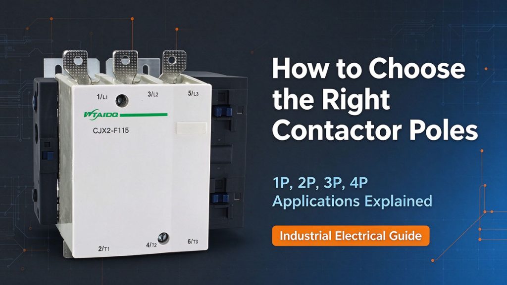
Number and arrangement of main power poles.
Permitted switching frequency and expected electrical endurance cycles.
Rated Operational Voltage vs Insulation Voltage
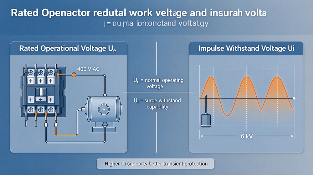
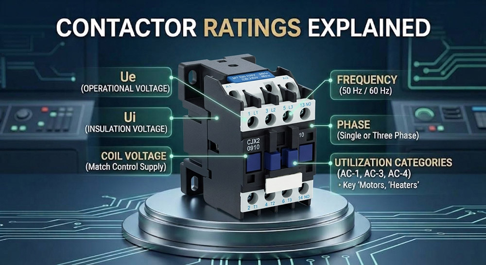
Two voltage markings commonly found on contactors are Ue and Ui. Although both are expressed in volts, they describe different properties and should not be used interchangeably.
Rated operational voltage (Ue) is the voltage associated with the contactor’s intended operation. It is used when determining the applicable operational current, switching performance, and load rating. A manufacturer’s stated current rating may vary with Ue and the utilization category.
Rated insulation voltage (Ui) is the reference voltage used in assessing the device’s insulation properties and related dielectric performance. It does not, by itself, tell you the voltage at which the contactor can switch a particular load.
Checking the Contactor Voltage Rating
When carrying out an AC contactor voltage check, start with the actual supply voltage and the load being controlled. Then confirm that the contactor’s operational voltage rating covers the application and that the corresponding current rating is sufficient.
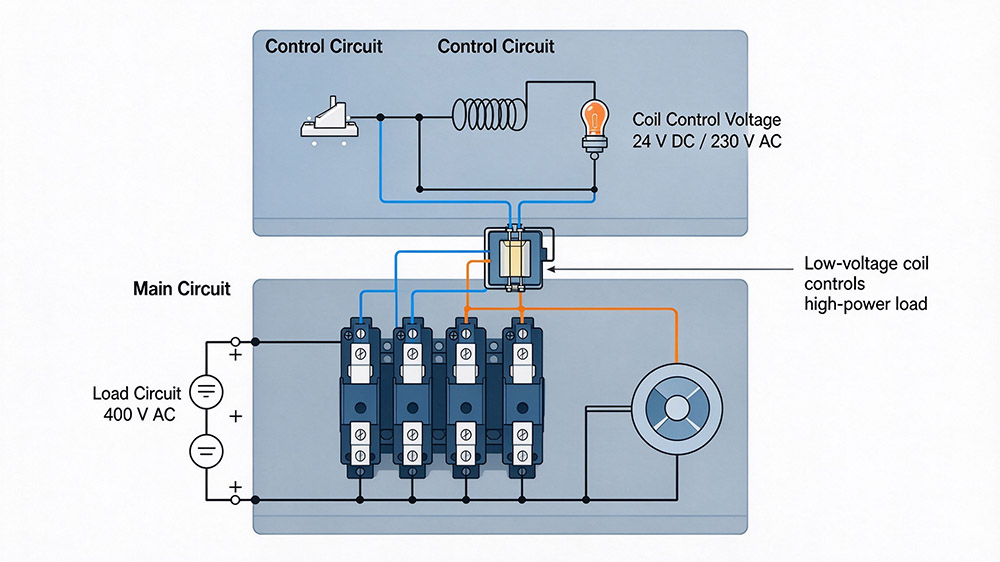
Do not confuse these ratings with the coil voltage. The main contacts and the coil serve different electrical functions, and their voltage specifications may be very different.
For example, a contactor can switch a three-phase 400 V motor while using a 24 V AC control coil. This arrangement is common in control panels because the main circuit supplies the motor, while a separate low-voltage control circuit energizes the coil.
Coil Control Voltage: What It Has to Match
The contactor coil creates the magnetic force that closes the main contacts. Its voltage must match the control circuit that energizes it, not simply the voltage of the equipment connected to the main contacts.
Common AC contactor coil voltage options include 24 V, 110 V, 120 V, 220 V, and 230 V AC. Some models also use DC coils, including 24 V DC.
How to Choose the Correct Coil Voltage
Start by identifying the control power supply. If a control transformer provides 24 V AC to operate the contactor, select a compatible 24 V AC coil. If the control system supplies 230 V AC, choose a coil specifically rated for that supply.
A contactor coil voltage chart can help narrow down the available options, but always confirm the actual voltage and frequency specified for the exact model.
| Control Supply | Typical Coil Selection |
|---|---|
| 24 V AC | 24 V AC coil rated for the supply frequency |
| 24 V DC | 24 V DC coil |
| 110 V AC | 110 V AC coil with matching frequency |
| 120 V AC | 120 V AC coil with matching frequency |
| 220–230 V AC | Coil rated for the actual supply and frequency |
The contactor coil voltage range should also be considered when the control supply fluctuates. Too little voltage can prevent reliable pickup or cause chatter, while excessive voltage can overheat or damage the coil. Check the manufacturer’s pickup and dropout limits rather than assuming that any voltage near the nominal value will work.
Phase Configuration and Phase Compatibility
Phase configuration describes the electrical supply and load arrangement. It also influences the number of main contacts required and the applicable voltage and current ratings.
Single-phase loads are commonly supplied through line and neutral conductors, or through two line conductors in certain systems. Three-phase motors use three phase conductors and typically require a contactor with three suitable main poles.
A practical selection guide is shown below:
| Application | Typical Contact Arrangement | What to Check |
|---|---|---|
| Single-phase heater | 1 or 2 poles, depending on the circuit | Switching arrangement, voltage, current and local requirements |
| Single-phase motor | 2 poles are commonly used | Motor current, starting duty and required isolation |
| Three-phase induction motor | 3 main poles | Line voltage, motor current and AC-3 rating |
| Reversing three-phase motor | Two appropriately interlocked contactors, usually 3 poles each | Phase reversal arrangement and AC-4 duty if applicable |
Some installations use two line conductors from a three-phase system, while other applications have specialized phase arrangements. Identify the actual supply rather than choosing a contactor based on the number of wires alone.
Also, do not confuse the number of poles with the number of phases. Poles describe the number of switching paths, while phase configuration describes the electrical supply.
Frequency: Why 50 Hz and 60 Hz Coils Are Not Interchangeable
Electrical frequency affects the magnetic operation of an AC contactor coil. Many products are designed specifically for 50 Hz, 60 Hz, or dual-frequency operation.
A coil marked 230 V AC, 50 Hz should not automatically be connected to a 230 V, 60 Hz supply. Likewise, a 60 Hz-only coil should not be assumed suitable for 50 Hz operation.
Frequency changes the relationship between voltage, magnetic flux, and coil impedance. An unsuitable combination can cause excessive heating, unreliable operation, or mechanical chatter. The actual outcome depends on the coil design and its permitted operating conditions.
Some contactors are explicitly rated for both 50 Hz and 60 Hz, allowing them to operate on either supply within the manufacturer’s stated limits.
Utilization Categories AC-1, AC-3 and AC-4
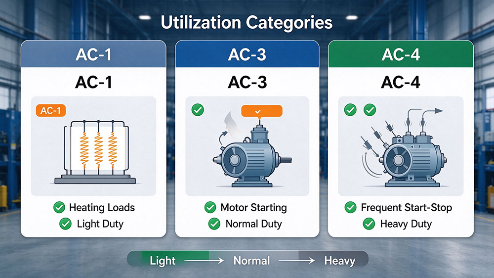
Utilization categories describe the switching conditions a contactor is designed to handle. They help explain why the same model can carry different rated operational currents for different applications.
AC-1 vs AC-3 Contactor Rating
AC-1 Duty
Generally applies to non-inductive or slightly inductive loads, such as resistive heating equipment. It imposes minimal mechanical and thermal stress during contact interruption.
AC-3 Duty
Generally applies to starting squirrel-cage motors and switching them off while running at rated speed. The contactor must safely withstand starting currents of 5 to 7 times rated current.
AC-4 Duty
Applies to severe motor switching duties, including inching (jogging), plugging, and rapid reversing. Interrupting full locked-rotor starting current produces extreme contact erosion.
| Category | Typical Application | Selection Consideration |
|---|---|---|
| AC-1 | Resistive heating loads | Check the AC-1 current at the intended voltage |
| AC-3 | Normal starting and stopping of induction motors | Check the motor’s rated current and AC-3 rating |
| AC-4 | Inching, plugging and frequent reversing | Check the AC-4 rating and required electrical endurance |
Reading a Contactor Nameplate
The nameplate brings together the information needed to assess a contactor’s suitability. Some markings describe electrical limits, while others identify the coil, contact arrangement, or applicable standards.
When checking AC contactor specifications, review the following items:
If a label shows several current values, identify the voltage and utilization category associated with each one. A single number without its rating conditions can be misleading.
A Selection Table That Puts It Together
The following contactor ratings chart provides a starting point for common applications. The values describe example system requirements, not guaranteed ratings for any specific contactor.
| Application | Main Supply | Coil Requirement | Utilization Category |
|---|---|---|---|
| Resistive heater | Single-phase, 230 V, 50 Hz | 24 V AC, 50 Hz control supply | AC-1 |
| Small three-phase motor | Three-phase, 400 V, 50 Hz | 24 V DC control supply | AC-3 |
| Standard motor starter | Three-phase, 400 V, 50 Hz | 230 V AC, 50 Hz control supply | AC-3 |
| Frequent motor inching | Three-phase, 400 V, 50 Hz | Compatible control supply | AC-4 |
| Export machine | Voltage depends on destination | Coil rated for the local control supply and frequency | Based on the actual load |
A Practical Selection Checklist
Use this sequence when comparing standard contactor ratings:
1. Identify the load type and its rated current or power.
2. Confirm the main supply voltage and phase configuration.
3. Select the correct utilization category.
4. Check the contactor’s operational current at the relevant voltage and category.
5. Match the coil voltage and frequency to the control supply.
6. Confirm the pole arrangement, switching frequency, and required electrical endurance.
7. Check the manufacturer’s installation requirements and the associated short-circuit and overload protection.
For an AC high voltage contactor, additional requirements apply. Medium-voltage and high-voltage equipment can use different designs, insulation systems, and switching technologies from conventional low-voltage contactors. Selection must follow the equipment’s specific voltage class, fault conditions, and manufacturer documentation rather than the rules for an ordinary motor starter.
Conclusion
Selecting the right contactor becomes much easier when you look beyond rated current. Check the operational voltage, insulation voltage, coil control voltage, phase configuration, frequency, and utilization category together. These specifications help you match the contactor to the actual load, avoid compatibility issues, and support reliable operation over time. Always verify the final selection against the manufacturer’s datasheet.
Looking for dependable contactors and low-voltage protection products? WTAIELE offers AC and DC contactors, circuit breakers, and other electrical protection solutions for industrial control and power distribution. Explore our AC contactor product range and find a suitable fit for your next project.
Frequently Asked Questions
Can I use a 230 V contactor on a 400 V supply?
It depends on which voltage the marking describes. If 230 V refers to the coil rating, the coil must receive its specified control voltage, while the main contacts must independently be rated for the 400 V application. If 230 V is the main-contact operational rating, do not assume the contactor is suitable for switching a 400 V load.
How do I check the correct AC contactor coil voltage?
Check the coil marking, product code, wiring diagram, and manufacturer’s datasheet. Measure the control supply using an appropriately rated meter and safe electrical procedures. Confirm both the voltage and frequency before energizing the coil.
Is a 50 Hz contactor coil compatible with 60 Hz?
Only if the manufacturer specifies that compatibility. A dual-frequency coil may support both supplies, while a single-frequency model may not. Never assume that matching voltage alone guarantees correct operation.
Why does a contactor have different AC-1 and AC-3 current ratings?
The categories represent different switching duties. Resistive loads generally impose less demanding switching conditions than induction motors. The appropriate current rating must match the actual load and operating conditions.
What is the difference between coil voltage and contactor voltage rating?
Coil voltage specifies the supply needed to operate the electromagnetic mechanism. The main-contact voltage rating describes the conditions under which the contactor can switch its connected circuit. Both must be checked independently.