Key Takeaways
Control & Automation
Relays are commonly used in control circuits, signal switching, automation, and low-current applications.
Power Load Switching
Contactors are designed for frequent switching of higher-power loads, including motors, heating equipment, and capacitor banks.
Technical Criteria
The main differences involve load capacity, contact design, arc suppression, utilization categories, and coil power consumption.
The One-Line Difference
Both devices can use an electromagnetic coil to open or close contacts. When the coil receives the appropriate voltage, the resulting magnetic field moves the contact mechanism, changing the electrical connection. When the coil is de-energized, the contacts normally return to their original position unless the device uses a latching mechanism.
The difference lies in how the devices are designed to handle electrical loads and switching conditions.
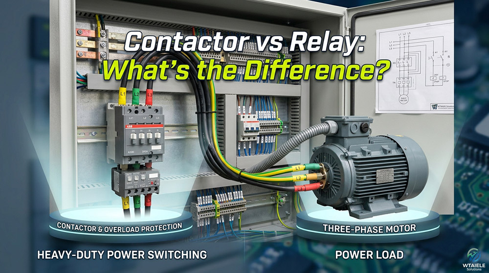
A relay might receive a signal from a programmable logic controller (PLC) and switch a small indicator lamp, control valve, or another relay coil. A contactor, by comparison, might receive a command from the same PLC and switch power to a three-phase motor.
In this arrangement, the relay or PLC manages the control logic, while the contactor handles the heavier electrical load.
Load Current and Breaking Capacity
One of the most visible differences between relays and contactors is their ability to carry and interrupt current.
General-purpose relays often operate in the milliampere range or at currents of a few amperes. Some power relays are rated for tens of amperes, so a fixed current threshold cannot define every relay.
Contactors are commonly available for loads ranging from several amperes to hundreds of amperes, with larger industrial models designed for even higher currents. Their actual capacity depends on the product, voltage, load type, and operating conditions.
The following examples illustrate typical applications rather than universal rating limits:
Signal Relay
Switching a sensor output or a low-power control signal.
Power Relay
Operating a small pump, fan, or electrical heating element within its specified ratings; explore options like the WTA1 power and time relay range.
Motor Contactor
Starting and stopping an industrial motor under its designated utilization category.
High-Current Contactor
Controlling larger heating systems, industrial machinery, or other substantial electrical loads.
The rated current alone does not tell the whole story. A device may carry a particular current continuously but be unable to interrupt that same current safely under demanding conditions.
Arc Suppression: Why Contactors Look Different
Opening an energized circuit can produce an electrical arc between separating contacts. The problem becomes more demanding when the device switches high currents or inductive loads, such as motors.
An arc can erode contact surfaces, generate heat, and shorten the service life of a switching device. If it is not controlled appropriately, it can also damage equipment.
What does an arc chute do?
Many contactors use an arc chute or arc chamber to help control the arc formed during switching. Depending on the design, the assembly divides the arc into smaller sections, lengthens it, cools it, or directs it away from the contact area so that it can be extinguished.
This design helps contactors interrupt the types of loads for which they are rated. It also contributes to their suitability for repeated switching in industrial environments.
Relay Arc Mechanisms
Relays may use contact spacing, contact materials, magnetic blowout mechanisms, sealed chambers, or other arc-control features. The design varies considerably between signal relays, power relays, and specialized switching relays.
Contact Arrangement
Relays and contactors can both have normally open (NO) and normally closed (NC) contacts. Their internal contact arrangements, however, usually reflect their different applications.
Relay Contacts
Relays often provide one or more contact sets for control logic. Depending on the model, these may include:
This flexibility makes relays useful for routing signals, isolating control interfaces, and implementing logic between different devices.
Contactor Main Contacts & Auxiliary Contacts
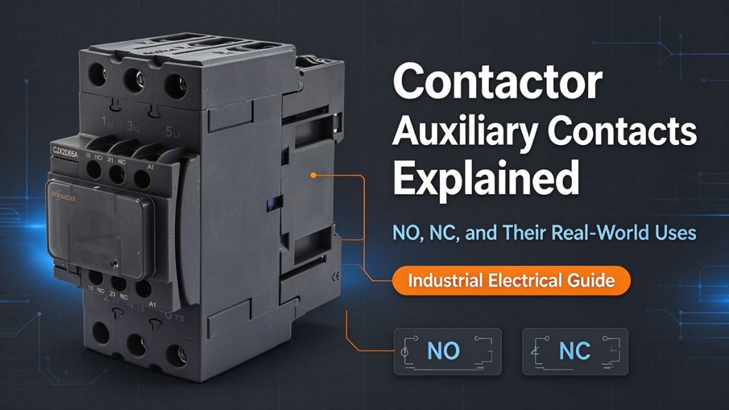
Contactors generally distinguish between main contacts and auxiliary contacts:
For example, pressing a start button may energize a contactor coil. An auxiliary NO contact then closes to maintain the coil circuit after the operator releases the button. Pressing the stop button interrupts the control circuit, allowing the contactor to release.
Utilization Categories
Current ratings become much more meaningful when considered alongside utilization categories.
Common AC utilization categories
| Category | Typical Application | Selection Consideration |
|---|---|---|
| AC-1 | Resistive or slightly inductive loads, such as resistance heating | Usually less demanding than motor switching |
| AC-3 | Starting squirrel-cage motors and switching them off while running | Accounts for motor starting and normal running conditions |
| AC-4 | Motor starting, inching, plugging, and other demanding switching duties | Requires consideration of more severe switching conditions |
AC-3 is commonly used for standard motor-control applications. AC-4 is relevant when motors must be jogged, reversed under demanding conditions, or switched in ways that involve frequent interruption of starting current.
Do relays have AC-3 and AC-4 ratings?
General-purpose relays are not normally selected using the contactor-specific AC-3 and AC-4 categories. Their suitability is established through the ratings and specifications applicable to the particular relay and load.
Specialized relays may have ratings for motor loads or other demanding applications, so the important point is not that a relay can never switch a motor. It is that a general-purpose relay should not be assumed suitable for a motor-control duty without supporting specifications.
Coil Power and Holding Current
Both devices need an operating mechanism, but their coil power consumption can differ.
When an electromagnetic relay or contactor operates, its coil generates the magnetic force needed to move and hold the contacts. The required power depends on the coil design, supply type, voltage, and operating state.
Pull-in power versus holding power
In many electromagnetic contactors, the coil requires more power during pull-in than during steady-state holding. Once the armature closes, the magnetic circuit changes, allowing the holding power to fall.
Some contactors use electronic coil-control systems to reduce steady-state consumption further.
Relays also vary. Small signal relays may use very little coil power, while power relays can require more. Latching relays may need only a brief pulse to change state rather than continuous coil energization.
When a Relay Is the Right Answer
A relay is often the practical choice when the circuit involves low or moderate power, compact installation requirements, or flexible control logic.
Common applications include:
For example, a temperature controller might use a relay output to signal that a temperature threshold has been reached. If the controlled heater draws a current beyond the relay’s suitable switching rating, the relay can instead command a properly rated contactor.
When a contactor is unnecessary
Using a contactor for every small control load can increase panel size, wiring complexity, and component cost without delivering a useful benefit.
If a properly rated relay can switch the load safely and reliably, a contactor may be unnecessary. A relay is also often more convenient for PCB mounting, compact control modules, and applications requiring multiple changeover contacts.
When You Must Use a Contactor
A contactor is generally the preferred choice when a load requires a dedicated power-switching device with appropriate electrical endurance and breaking performance.
Electric Motors
Contactors are widely used in pumps, compressors, conveyors, fans, and other industrial machinery. Select a model rated for the motor’s operating conditions, including starting current and switching duty.
Heating Equipment
Industrial heaters and resistance-heating systems may use contactors to switch substantial loads. AC-1 ratings are often relevant for resistive loads, but the actual equipment and operating conditions must be checked.
Capacitor Banks
Switching capacitors can create high transient inrush currents. Capacitor-switching applications may require contactors specifically designed for that duty, sometimes with additional inrush-limiting provisions.
Lighting and Distribution Loads
Larger lighting circuits and other power loads may also use contactors when remote switching, centralized control, or frequent operation is required.
A contactor is not a circuit breaker
Choosing a contactor does not remove the need for suitable protection.
A contactor primarily makes and breaks a circuit during normal operation. A circuit breaker provides protection against specified overcurrent or short-circuit conditions, depending on its design and rating. Motor overload protection may require a separate overload relay or an appropriate motor protection device.
The protection arrangement must be coordinated with the contactor and the connected load. Contactors are not generally intended to interrupt short-circuit currents unless the particular device and system are specifically designed and rated for that purpose.
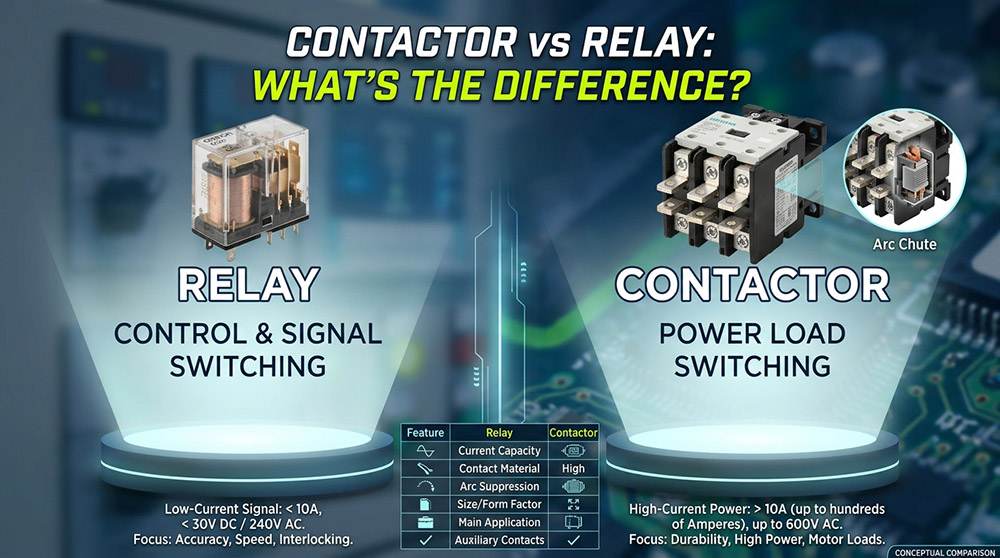
Side-by-Side Comparison Table
The following comparison between relay and contactor summarizes the main selection points:
| Feature | Relay | Contactor |
|---|---|---|
| Main Purpose | Control, signal, and suitable low-power switching | Power-load switching |
| Typical Current Range | Often milliamperes to several amperes; power relays can be higher | Commonly several amperes to hundreds of amperes |
| Contact Design | Often optimized for control flexibility and compactness | Main power contacts with optional auxiliary contacts |
| Arc Management | Depends on relay type and rating | Often includes dedicated arc-control features (e.g., arc chutes) |
| Motor Switching | Only when specifically rated for the application | Commonly used with suitable motor-duty ratings |
| Utilization Categories | Uses ratings applicable to the relay type | May use standard categories such as AC-1, AC-3, and AC-4 |
| Coil Consumption | Varies by design and operating mode | May have higher pull-in power and reduced holding power |
| Typical Installation | PCB, plug-in socket, or control panel DIN-rail | Motor-control panel or power-switching assembly |
| Common Applications | Signals, automation logic, small loads | Motors, industrial heaters, capacitor banks, and larger loads |
Contactor vs Relay Summary
These devices are sometimes confused because both can affect whether current flows through a circuit. Their primary functions are different:
Relay Function
Switches a circuit in response to a control signal, within its ratings, providing flexible logic and electrical isolation.
Contactor Function
Switches high-power electrical loads, often under frequent and demanding operating conditions.
Conclusion
Choosing the right switching device comes down to the load, operating conditions, and level of control required. A relay is a practical choice for signals and smaller control circuits, while a contactor is better suited to demanding power-switching applications.
Frequently Asked Questions
What is the main difference between a contactor and a relay?
A relay is commonly used for signal switching, control logic, and suitable low- or moderate-power loads. A contactor is designed primarily for switching power loads and often provides more robust contact and arc-control arrangements. The exact distinction depends on the device’s ratings and intended application.
Can a relay replace a contactor?
Sometimes, but only if the relay is specifically rated for the load, operating voltage, inrush current, breaking duty, and switching frequency. A general-purpose relay should not replace a motor contactor simply because its nominal current rating appears sufficient.
Can a contactor provide short-circuit protection?
A standard contactor is not a substitute for a circuit breaker or fuse. Suitable short-circuit protection must be provided and coordinated with the switching equipment. Overload protection may also be required for motor applications.
Why are AC-3 and AC-4 ratings used for contactors?
These utilization categories describe particular motor-switching duties. AC-3 generally covers starting squirrel-cage motors and switching them off while running, whereas AC-4 covers more demanding operations such as inching and plugging. The required category depends on how the motor will actually be operated.
Should I choose a relay or a contactor for a heater?
For a small heater, a relay may be suitable if its switching and electrical ratings cover the application. For a higher-power heater or a circuit requiring frequent switching, a suitably rated contactor is often a better option. Check the load current, voltage, switching frequency, and applicable utilization category before making the selection.