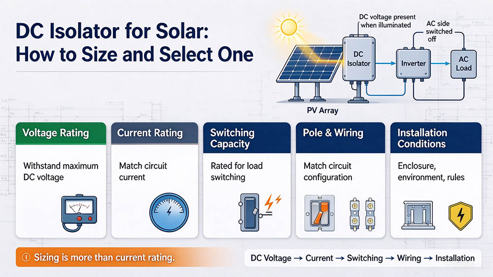
A solar PV system can continue producing DC electricity whenever its panels receive sunlight, even when the AC side is switched off. A correctly selected DC isolator provides a practical way to separate part of the system for inspection or maintenance. Choosing one involves more than matching a current rating: voltage, switching capacity, wiring configuration, and installation conditions all need to fit the actual PV circuit.
What a DC Isolator Does in a PV System
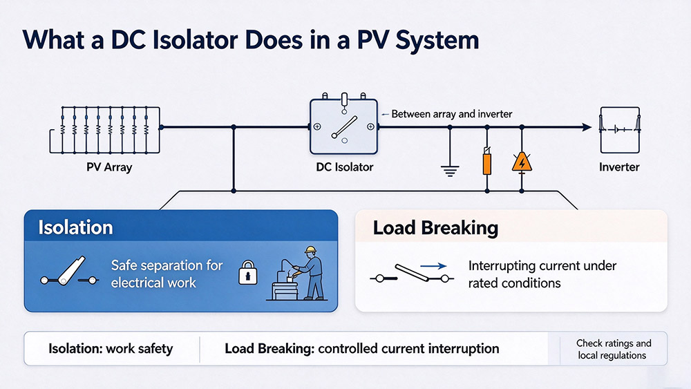
A DC isolator, also called a DC switch-disconnector, separates a section of a solar photovoltaic (PV) circuit from the rest of the electrical system. It is commonly installed between the PV array and the inverter, although its exact position depends on the system design and local regulations.
Isolation vs. Load Breaking
Isolation and load breaking are related but different functions:
Isolation
Separates a circuit so that electrical work can be carried out under the required safe-working procedures, ensuring zero physical contact with live conductors.
Load Breaking
Opens a circuit while full direct current is flowing, using a specialized contact and arc-chamber structure designed to interrupt that current safely.
A simple disconnector may be intended only for operation when no current is flowing. A switch-disconnector suitable for PV applications can provide both isolation and load switching when its ratings and utilization category permit it.
Why AC Breakers Cannot Be Used on DC
The main difference between AC and DC switching is how current behaves when contacts open.
In an AC circuit, the current naturally passes through zero during each cycle. This helps the electrical arc between separating contacts extinguish. In a DC circuit, current does not have the same periodic zero-crossing, so an arc can continue after the contacts begin to separate.
A sustained arc can damage contacts, overheat internal components, and create a severe fire hazard. At high PV string voltages, interrupting the current without suitable arc-control measures becomes particularly challenging.
DC-rated devices are designed to manage this condition through features such as appropriate contact spacing, arc-control structures, and specified pole configurations.
Before choosing a device, verify three essential criteria:
Maximum System Voltage
Its rated DC operational voltage meets or exceeds the system’s maximum calculated design open-circuit voltage.
DC Breaking Capacity
Its rated continuous current and DC load-breaking capability satisfy the prospective circuit fault requirements.
Certified Application Scope
Its product documentation and testing certifications explicitly cover the intended PV application and ambient switching conditions.
Isolator vs. DC Breaker vs. DC Fuse
Although these devices may appear in the same solar installation, they perform different jobs. Choosing one does not automatically eliminate the need for the others.
| Device | Main Function | Selection Focus |
|---|---|---|
| DC Isolator | Provides a designated point for circuit isolation and, when rated accordingly, manual load switching | Maximum DC voltage, operating current, switching category, and pole configuration |
| DC Circuit Breaker | Opens a circuit automatically when specified overcurrent conditions occur; suitable models can also provide manual switching | Rated voltage, current, trip characteristics, and DC interruption capability |
| DC Fuse | Interrupts excessive current when the fuse element operates | Fuse rating, voltage, breaking capacity, and suitability for PV circuits |
A DC isolator is not automatically an overcurrent protection device. If a fault occurs, it may not trip on its own. A DC circuit breaker or fuse provides overcurrent protection when correctly selected and installed.
For example, the WTAIELE product range includes the WTM7-63 DC circuit breaker, the WTDS DC fuse, and the WTSP-D40 DC surge protective device (SPD). These products address different protection needs within a DC electrical system.
Sizing by String Voltage and Current
Correct sizing starts with the PV module datasheet and the actual string configuration. Two values need particular attention: maximum open-circuit voltage and design current.
Step 1: Calculate the Maximum String Voltage
A simplified calculation is:
For a preliminary illustration, assume 10 modules, each with an STC open-circuit voltage of 40 V, and a correction factor of 1.2:
Step 2: Calculate the Design Current
Using a factor of 1.25 for illustration, assume two parallel strings, each with a short-circuit current of 14 A:
Step 3: Check Temperature and Switching Ratings
A device’s nominal current rating may not remain available under every installation condition. High ambient temperatures, direct sunlight, and heat trapped inside an enclosure can reduce its permissible operating current.
Check the manufacturer’s temperature-derating data and select a rating that remains adequate under the expected conditions. Also confirm the device’s DC breaking capability at the calculated voltage. A switch may have a sufficient continuous-current rating but still be unsuitable for interrupting that current at the required DC voltage.
Finally, verify the number of poles and the permitted wiring configuration. If the circuit design requires both positive and negative conductors to be disconnected, the device must provide that function in accordance with the applicable requirements.
Polarity and Wiring
DC polarity deserves careful attention during installation. Unlike AC circuits, a PV string has defined positive and negative conductors, and the switching device may have specific terminal markings or connection requirements.
Before wiring, check the manufacturer’s diagram for the following technical details:
Some DC switching devices require multiple poles to be connected in a prescribed series arrangement to achieve the rated voltage and arc interruption performance. Simply connecting the cables to the nearest available terminals may not provide the intended performance.
Common Installation Mistakes
Even a correctly rated component can perform poorly when installed incorrectly. These are critical issues worth checking during installation and inspection:
| Common Mistake | Potential Risk | Recommended Practice |
|---|---|---|
| Switching Under Load With an Unsuitable Device | Opening a PV circuit under load can produce a sustained electrical arc resulting in fire. | Use only a switch-disconnector rated for the intended load-breaking duty, and follow the prescribed operating sequence. |
| Installing the Isolator in the Wrong Position | The device may fail to isolate the intended section during routine maintenance. | Follow system design, inverter instructions, and local electrical requirements at array, inverter, or combiner locations. |
| Ignoring Parallel Strings | Sizing the isolator based on a single string creates dangerous thermal overload when multiple strings parallel upstream. | Account for the combined current of parallel strings and the increased voltage of series-connected modules when selecting the isolator. |
| Overlooking Environmental Conditions | Rain, dust, UV exposure, and trapped heat degrade switching mechanisms and shorten service life. | Choose an enclosure with an appropriate ingress protection (IP) rating, UV resistance, and sealed cable glands. |
| Skipping Final Inspection | Loose terminals, mismatched conductors, and damaged enclosures compromise safety. | Before commissioning, verify wiring against the approved diagram, torque all terminals, and complete insulation tests. |
| Neglecting Regular Inspections | Undetected overheating, internal oxidation, and moisture ingress can trigger catastrophic failures. | Inspect the isolator regularly for visible casing damage, heat discoloration, moisture, and smooth mechanical action. |
Conclusion
Selecting a DC isolator for solar comes down to matching the device to the real operating conditions of the PV system. Calculate the maximum string voltage, determine the design current, account for temperature, and verify the switching configuration before installation. A well-matched isolator, working alongside the appropriate circuit breakers, fuses, and surge protection, helps keep a solar installation easier to maintain and safer to operate.
For reliable DC protection components, explore the WTAIELE product range, including DC circuit breakers, DC fuses, and surge protective devices, to find options for your solar project’s protection requirements.
Frequently Asked Questions
Does every solar PV system need a separate DC isolator?
Not necessarily. The required isolation arrangements depend on the inverter design, the installed switching equipment, and local electrical regulations. Some inverters include an integrated DC switch-disconnector, while other installations require external equipment. Confirm the applicable requirements before deciding whether an additional isolator is needed.
How do I choose between a 2-pole and a 4-pole DC isolator?
The choice depends on the number of circuits being switched, the required isolation arrangement, and the manufacturer’s approved wiring configuration. A 2-pole device may be used to disconnect both conductors of a single circuit, while a 4-pole device can accommodate other arrangements where its ratings permit. Pole count alone does not establish the voltage or current capacity.
Can a DC isolator replace a DC circuit breaker?
No, not unless the device is specifically designed and rated to provide the required additional protection. A standard isolator provides circuit separation and may permit load switching, but it does not automatically trip under overload or short-circuit conditions. Use the appropriate protective devices for the system.
Should I size a DC isolator using operating current or short-circuit current?
Both values matter, but they serve different purposes in the design. Operating current helps establish the continuous-current requirement, while short-circuit current and the applicable correction factors help determine the required design current and protection arrangements. The final selection must also account for DC switching ratings, temperature derating, and local standards.
What should I check before purchasing a DC isolator?
Confirm the maximum temperature-corrected PV string voltage, design current, DC switching capability, pole arrangement, environmental rating, and compatibility with the conductors. Review the product datasheet and installation instructions, and check that the equipment meets the standards and certification requirements for the destination market.