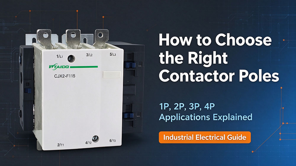
A contactor may look like a straightforward component, but choosing the wrong pole configuration can complicate wiring and affect how a circuit operates. Understanding the difference between 3-pole and 4-pole contactors helps engineers, electricians, and equipment buyers select a device that fits the electrical system without unnecessary complexity.
Poles Are Not Phases
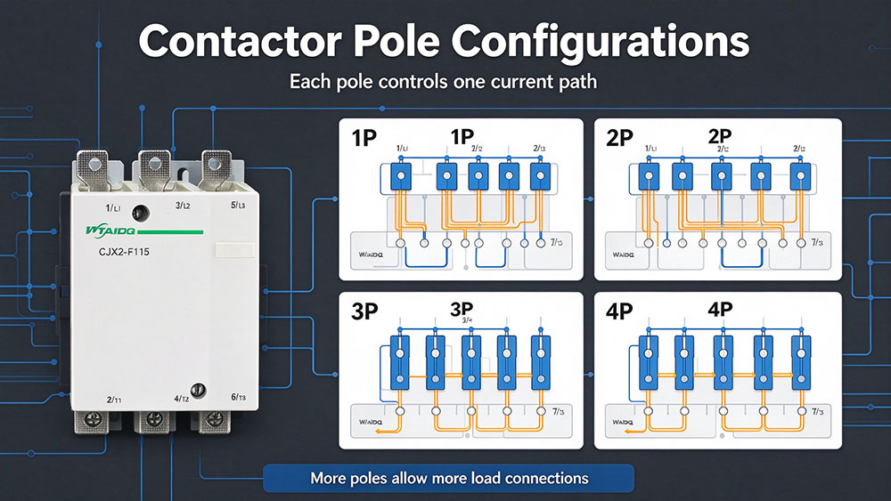
Poles describe the number of separate electrical paths that the contactor can switch, while phases describe the arrangement of the power supply.
A three-phase system has three phase conductors, commonly identified as L1, L2, and L3. Depending on the system, it may also include a neutral conductor. This is why a three-phase installation can use either a 3-pole or a 4-pole contactor.
What Does the Pole Count Mean?
When the contactor coil receives its control voltage, the operating mechanism changes the state of its main contacts. When the coil is de-energized, the contacts return to their normal state, assuming a conventional non-latching contactor.
Each main pole switches a separate conductor. In a typical normally open power contact, the circuit closes when the contactor energizes and opens when it releases.
| Configuration | Typical Switched Conductors | Common Applications |
|---|---|---|
| Single-pole | One conductor | Simple single-phase circuits and control applications |
| 2-pole | Two conductors | Single-phase circuits requiring two switched conductors |
| 3-pole | Three phase conductors | Three-phase motors and industrial loads |
| 4-pole | Three phases plus neutral, or four other designated conductors | Neutral switching and specialized power-control arrangements |
Single-Pole Contactors
A single pole provides one switched power path. This makes a single-pole contactor suitable for certain simple loads, particularly when only one conductor needs to be switched and the system design permits that arrangement.
Typical examples include some resistive loads, small electrical circuits, and dedicated switching arrangements in which one conductor is controlled by the contactor. However, the term “single-pole contactor” does not mean that every single-phase appliance can safely be controlled by switching only one conductor.
When Is a Single Pole Enough?
The answer depends on the supply arrangement, earthing method, load, and required isolation. In some systems, a single-pole contactor can control a permitted line conductor while the neutral remains continuously connected. In others, both current-carrying conductors must be switched to meet the equipment design or isolation requirements.
For a small motor or appliance, also check the starting current and utilization category. A contactor that can carry the normal operating current may not be suitable for repeatedly switching an inductive load.
If two conductors must be disconnected together, a 2-pole device may be more suitable.
2-Pole vs 3-Pole Contactor
A 2-pole contactor is commonly used in suitable single-phase circuits, whereas a 3-pole contactor is generally selected for three-phase loads. A three-pole contactor may also be used in certain single-phase arrangements if the manufacturer’s instructions permit the intended connection. Unused poles must be handled according to the device documentation rather than improvised wiring practices.
3-Pole Contactors
A 3-pole contactor is a standard choice for controlling three-phase motors and other three-phase loads. Its three main contacts switch L1, L2, and L3 together through a mechanically linked operating mechanism.
Because many three-phase motors do not require a neutral conductor, a 3-pole contactor provides the switching arrangement needed without adding a fourth main contact.
Common Applications of a 3-Pole Contactor
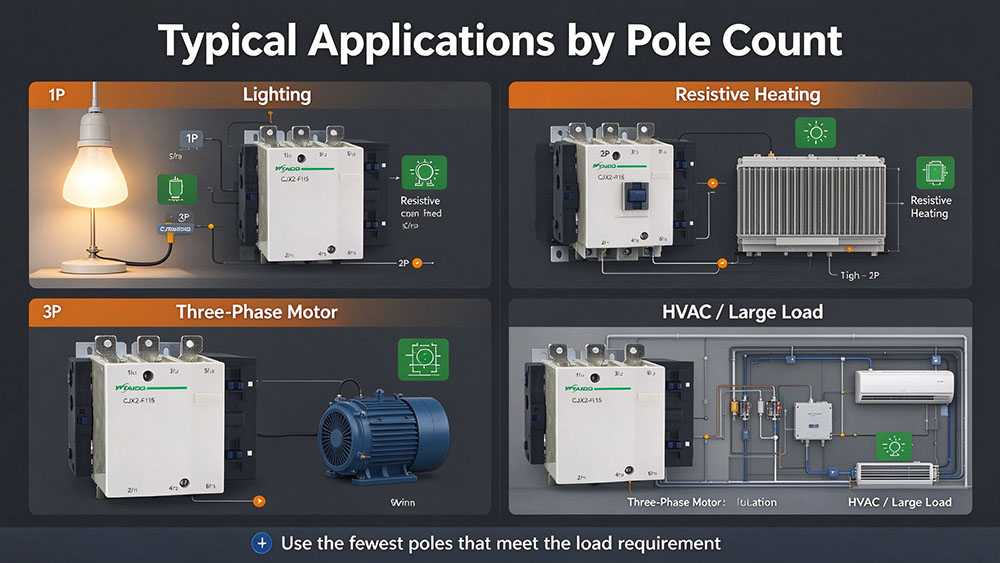
Three-pole contactors are widely used in motor starters, pumps, fans, compressors, conveyors, machine tools, and industrial heating equipment. They can also form part of a wider control system involving overload relays, protective devices, push buttons, and programmable controllers.
The contactor should be selected according to the actual duty. For example, motor switching requires attention to the motor’s rated power, operating voltage, full-load current, starting conditions, and switching frequency. A resistive heating load may have different selection requirements from a motor of the same nominal current.
3-Pole Contactor Wiring Diagram
A typical three-phase motor control arrangement has three power connections on the supply side and three corresponding connections on the load side.
| Contactor Terminal | Typical Connection |
|---|---|
| 1/L1 | Incoming phase L1 |
| 3/L2 | Incoming phase L2 |
| 5/L3 | Incoming phase L3 |
| 2/T1 | Outgoing connection to motor terminal U |
| 4/T2 | Outgoing connection to motor terminal V |
| 6/T3 | Outgoing connection to motor terminal W |
| A1 and A2 | Contactor coil control supply |
4-Pole Contactors
A 4-pole contactor has four main switching paths operated by the same mechanism. In a three-phase, four-wire system, the usual arrangement is L1, L2, L3, and neutral. The fourth pole can open or close the neutral path along with the phase paths when the contactor is designed and wired for that purpose.
Four-pole contactors are useful when the circuit requires more than the three phase connections alone. Applications may include certain power distribution arrangements, generator systems, and switching circuits in which the neutral must be disconnected with the phases.
One common application is a three-phase system supplying a mixture of three-phase and single-phase loads.
Another application is a power-control system with specific neutral-switching requirements.
4-Pole Contactor Wiring Diagram
For a typical three-phase, four-wire arrangement, the incoming conductors connect to the four line-side terminals, and the corresponding load-side terminals connect to the equipment.
| Pole | Typical Line-Side Connection | Typical Load-Side Connection |
|---|---|---|
| Pole 1 | L1 | Load L1 |
| Pole 2 | L2 | Load L2 |
| Pole 3 | L3 | Load L3 |
| Pole 4 | N | Load N |
4-Pole Contactors for Different Load Arrangements
A four-pole model may offer flexibility where the control panel needs all four conductors switched by one device. It can also reduce the need for separate switching components, depending on the application.
For product selection, the WTAIELE 4P Contactor Series provides a starting point for comparing available configurations. Individual models include the CJX2-1204 4P contactor, CJX2-2504 4P contactor, CJX2-6504 4P contactor, and CJX2-9504 4P contactor.
Switching a Neutral: What Changes?
In a three-phase, four-wire system, the neutral may carry the imbalance between single-phase loads. Its current depends on the connected loads and their distribution across the phases. Harmonics from certain electronic loads can also increase neutral current, so the neutral conductor and its switching contact must be appropriately rated.
Neutral Current and Contact Ratings
A fourth pole should not be assumed to have the same current-carrying capacity as the other three poles unless the product specifications confirm it. Some contactors offer different contact arrangements, and the ratings can depend on the model and operating category.
The design should account for the expected neutral current, the load type, the switching frequency, and any applicable requirements for isolation and protection. Where nonlinear loads or significant harmonic currents are present, a qualified designer should assess the neutral conductor and contact ratings.
Neutral Switching and Electrical Safety
Whether a neutral should be switched depends on the earthing arrangement, the source configuration, and the relevant installation rules. Some systems require a solid, unswitched neutral, while others use switched-neutral arrangements. Incorrect neutral switching can create unwanted current paths, interfere with residual-current or ground-fault protection, or produce unsafe operating conditions.
A contactor also does not replace a circuit breaker, fuse, isolator, or protective relay. These devices have different functions. The contactor performs routine switching, while the protective devices provide protection and isolation according to their ratings and design.
Can You Use a 4-Pole Contactor on a 3-Phase Load?
A 4-pole contactor can be used with a three-phase load when its ratings and contact configuration suit the application. The fourth pole may remain unused if the manufacturer permits that arrangement, or it may switch a fourth conductor when the circuit requires it.
For a standard three-phase motor without a neutral connection, the three phase conductors can be connected through the three appropriate main poles. The remaining pole should be left unconnected or handled exactly as the manufacturer specifies. Do not bridge terminals or use the fourth pole for an unrelated circuit without confirming that the device’s design permits it.
Auxiliary Contacts and Pole Count
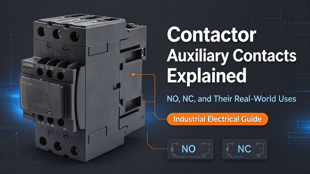
Auxiliary contacts are used in control circuits rather than as the main load-switching contacts. They can provide feedback to a controller, maintain a contactor’s energized state through a holding circuit, or support electrical interlocking between devices.
An auxiliary contact does not normally count toward the main power pole count. A 3-pole contactor with auxiliary contacts still has three main power poles, even if it includes one normally open auxiliary contact and one normally closed auxiliary contact.
How Auxiliary Contacts Work
Auxiliary contacts are commonly identified as normally open (NO) or normally closed (NC). In conventional IEC terminal numbering, 13–14 is often used for a normally open auxiliary contact, while 21–22 is commonly used for a normally closed contact.
For example, a 3-pole contactor with auxiliary contacts can switch three motor phases while using an auxiliary contact to send an operating signal to a controller. Another auxiliary contact may be used in a control interlock to prevent two incompatible contactors from energizing simultaneously.
Selection Flowchart
Choosing between three and four poles becomes easier when the selection process starts with the circuit rather than the product name. Identify the supply conductors, determine whether neutral switching is required, and then verify the contactor’s ratings and operating conditions.
A Practical Selection Process
| Selection Question | Recommended Direction |
|---|---|
| Is the load single-phase and does the design require only one conductor to be switched? | Consider a single-pole contactor if permitted by the circuit design. |
| Is the load single-phase and must two conductors be switched together? | Consider a suitable 2-pole contactor. |
| Is the load a conventional three-phase motor with no neutral switching requirement? | Start with a 3-pole contactor. |
| Is the system three-phase, four-wire, and does the design require the neutral to be switched? | Evaluate a 4-pole contactor with a suitable fourth-pole rating. |
| Is the contactor part of a generator or source-transfer arrangement? | Confirm the neutral, grounding, interlocking, and transfer requirements before selecting the pole count. |
| Are additional status or interlocking signals needed? | Check the available auxiliary contacts separately from the main poles. |
Conclusion
Choosing between a 3-pole and a 4-pole contactor starts with understanding which conductors need to be switched. A 3-pole model is a practical choice for many three-phase motor circuits, while a 4-pole model offers an additional switched path for applications that require it. Confirm the load, ratings, wiring, neutral arrangement, and protection requirements before finalizing the selection.
For dependable low-voltage electrical control, explore WTAIELE’s contactor range and compare the available configurations to find a suitable fit for your next project.
Frequently Asked Questions
What is the main difference between a 3-pole and a 4-pole contactor?
A 3-pole contactor switches three electrical paths, usually the three phases of a three-phase supply. A 4-pole contactor switches four paths, often the three phases and neutral. The correct choice depends on the circuit and whether neutral switching is required.
Can a 3-pole contactor be used for a single-phase load?
In some applications, yes, if the manufacturer’s instructions permit the connection and the contactor is rated for the load. However, the number of conductors that must be disconnected and the applicable electrical rules should be checked before installation.
Does a 3-pole contactor with auxiliary contacts become a 4-pole contactor?
No. Auxiliary contacts are separate from the main power poles. A three-pole contactor remains a three-pole model when auxiliary contacts are added, unless its main power-contact configuration itself is changed by a manufacturer-approved arrangement.
What should a 4-pole contactor wiring diagram show?
It should identify the four main contact paths, their line-side and load-side terminals, and the intended conductor connections. If the fourth pole switches neutral, the diagram should clearly show the neutral path. The coil circuit and auxiliary contacts should also be identified where relevant.
How do I compare 4-pole contactor prices?
Compare models with equivalent current ratings, utilization categories, coil voltages, contact arrangements, accessories, and certifications. Confirm whether the quoted product includes auxiliary contacts and other requested features. Comparing the technical specifications alongside the quoted price gives a more useful basis for selection.